
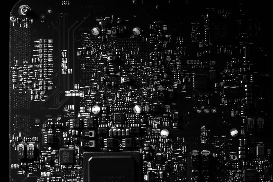
Reading a circuit board starts with understanding that it is a flat map of electrical connections. Every component, trace, and label on the board exists to move electricity from one place to another in a controlled way. For a beginner, the goal is not to understand every component at once. The goal is to learn how to identify the board’s basic parts, follow the copper pathways, and use the printed labels to figure out what each section does.
What Are The Main Parts Of A Circuit Board?
Every circuit board has a few core physical parts you will see again and again. The board itself is usually made of fiberglass and resin, often green but sometimes red, blue, or black. This base is called the substrate. It is an insulator, meaning it does not conduct electricity.
On top of the substrate, thin lines of copper are etched into place. These are called traces. Traces are the wires of the board. They carry electrical signals and power between components. The copper traces are covered by a thin layer of solder mask, which is the colored coating you see. The solder mask protects the copper and prevents accidental contact between traces.
Components are soldered onto the board. These include resistors, capacitors, diodes, and integrated circuits (ICs). Each component has a specific job, and its position on the board is not random. The layout is designed so that signals travel the shortest practical distance between parts.
You will also see small holes in the board. These are called vias or plated through-holes. They allow traces to move from one layer of the board to another. Most modern boards have multiple layers of copper stacked inside the substrate. Vias are the connection points between those layers.
How Do You Identify Components On A Circuit Board?
Components are identified by their physical shape and by the markings printed on the board. Every component has a reference designator printed next to it in white text. This is a code that tells you what type of component it is.
- R stands for resistor.
- C stands for capacitor.
- D stands for diode.
- Q stands for transistor.
- U stands for integrated circuit.
- L stands for inductor.
- J or P stands for connectors or jumpers.
These letters are followed by a number, like R12 or C3. The number is just a label. It does not tell you the value of the component. It only tells you where it is on the board.
The components themselves also have markings. Resistors often have colored bands that encode their resistance value. Capacitors may have a number printed on them, like 104, which is a code for capacitance. Integrated circuits have a part number printed on top, such as a model number from a manufacturer like Texas Instruments or Intel. You can look up that part number online to find a datasheet, which is the official document describing exactly what the chip does.
How To Read A Circuit Board For Beginners: Following The Traces
Traces are the key to understanding how a board works. To read them, you need to look closely at the board’s surface. A trace looks like a thin, shiny line running between components. They often branch off and change direction at right angles.
Follow a trace from a connector pin and you will see where that signal goes. This is the most direct way to understand the function of a circuit. For example, a trace that runs from a power connector to a voltage regulator, and then to many other components, is clearly a power distribution path. A trace that runs between two specific chips is likely carrying data between them.
When the board has multiple layers, you cannot see all the traces from the top. Some traces are buried inside the board. In that case, you use the vias to track the signal path. A via is the small hole with a ring of copper around it. When a trace ends at a via, the signal goes to another layer. You can often find the continuation of that trace on the other side of the board.
Do not expect to trace every single connection. Complex boards can have thousands of traces. The skill is learning to trace the important ones: power inputs, ground connections, and signal paths between major chips.





What Is A Schematic And How Does It Relate To The Board?
A schematic is the diagram of the circuit. It shows the electrical connections using symbols instead of physical parts. The circuit board is the physical realization of that schematic. Every connection on the schematic exists as a trace on the board.
For a beginner, the schematic is the best tool for understanding a board. It shows you the intended function of each component and how they are connected. The board itself only shows you physical layout. Without the schematic, you are guessing at the designer’s intent.
To use a schematic, you match the reference designators. If the schematic shows R12 connected to pin 3 of U1, you can find R12 on the board and trace the copper line to see where it physically goes. This cross-referencing is the core skill of circuit board reading.
If you do not have a schematic, you can still learn a lot. Look for the power section, the processor, and the connectors. Identify which components are large, because large components often handle higher power or voltage. Look for the ground plane, which is usually a large area of copper that connects to many components. Ground is the reference point for all voltages on the board.
Why Are Some Components Bigger Than Others?
Component size is directly related to the electrical job it performs. Resistors and capacitors come in different physical sizes based on their power rating and voltage rating. A large resistor can safely dissipate more heat than a small one. A large capacitor can store more charge.
Integrated circuits are sized by the number of pins they need and the complexity of the silicon inside. A small chip with eight pins is much simpler than a large chip with hundreds of pins. The large chip is likely a processor, memory controller, or other complex logic device.
Transformers and inductors are often the largest components on a board. They contain coils of wire and sometimes metal cores. They are used in power supplies to convert voltage levels. If you see a large, heavy component on a board, it is often part of the power conversion circuit.
Connectors vary in size based on the current they carry and the number of signals they handle. A USB connector has four pins. A power connector for a computer motherboard can have twenty or more pins. The size of the connector tells you how much data or power passes through it.
What Do The Numbers And Symbols On A Circuit Board Mean?
Beyond the component labels, boards have other markings. You will see a manufacturer logo, a board revision number, and a date code. The revision number matters because a board may have design changes between versions. If you are troubleshooting, you need to know which revision you have.
Near the edge of the board, you may see a series of small text labels like +5V, GND, or TX and RX. These are test points or labeled pins. They tell you the expected voltage or signal at that location. These labels are invaluable when you are learning because they give you a starting point for measurement.
Some boards have a small dot or a notched corner near a chip. This marks pin 1 of the integrated circuit. Pin numbering always starts at the marked corner and goes counterclockwise. Knowing where pin 1 is allows you to identify all other pins on the chip.
You may also see a small battery symbol or a fuse symbol printed on the board. These indicate the location of a battery holder or a fuse. Fuses are safety devices that break the circuit if too much current flows. They are often replaceable.
What Tools Do You Need To Read A Circuit Board?
Start with your eyes and good lighting. Many traces and labels are small. A magnifying lamp or a jeweler’s loupe makes the job much easier. A digital camera on your phone can zoom in on tiny text and capture an image for reference.
A multimeter is the most useful electronic tool. It measures voltage, resistance, and continuity. Continuity mode tells you if two points are electrically connected. This is how you verify a trace path when you cannot see it clearly. You place one probe on a component pin and the other probe on another point. If the meter beeps, they are connected.
You do not need a soldering iron to read a board. You only need it if you plan to repair or modify the board. For reading and understanding, a multimeter and a good light source are sufficient. As you gain experience, you may want a microscope for fine-pitch components, but that is not necessary for beginners.
Common Mistakes Beginners Make
The most common mistake is trying to understand every component at once. A board with hundreds of parts is overwhelming. Instead, focus on one section at a time. Identify the power input, find the main processor, and trace only a few key signals.
Another mistake is assuming that the physical layout matches the schematic layout. It does not. The schematic is organized for clarity. The board is organized for electrical performance and manufacturing ease. A component that appears next to another on the board may not be connected to it at all.
Do not confuse a via with a component pad. A via is a hole used only for layer-to-layer connections. A component pad is a hole or surface area where a component leg is soldered. They look similar but serve different purposes. If you try to solder a component into a via, you will damage the board.
Finally, do not touch the board while it is powered. Capacitors can hold a dangerous charge even after the power is off. Always discharge the board and unplug it before you inspect it closely. This is not optional. It is a safety requirement.
Frequently Asked Questions
What is the easiest way to identify a component on a circuit board?
Look for the white reference designator printed next to the component, such as R for resistor or C for capacitor. Then match that label to the schematic or a component datasheet.
Do I need a schematic to read a circuit board?
No, but it makes the job significantly easier. Without a schematic, you can still identify components, trace power paths, and find ground connections, but you will not know the intended function of every circuit.
What does a via look like on a circuit board?
A via looks like a small hole with a shiny copper ring around it. It connects traces on different layers of the board, allowing signals to move from the top layer to inner or bottom layers.
Is it safe to touch a circuit board with my hands?
Only when the board is completely unplugged and discharged. Many components can be damaged by static electricity, and capacitors can hold a dangerous charge. Always handle boards by the edges and ground yourself before touching sensitive parts.
