
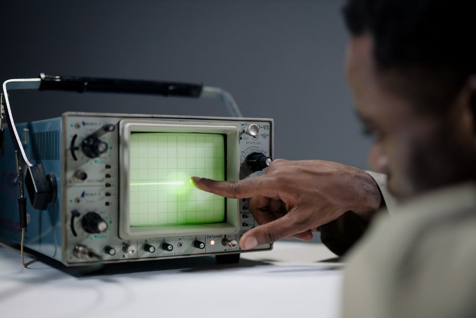
Measuring gain with an oscilloscope is a straightforward process of comparing an input signal to an output signal. You measure the amplitude of the signal going in, then measure the amplitude of the signal coming out of the circuit. The gain is the output amplitude divided by the input amplitude. This gives you a number that shows how much a circuit amplifies a signal, and it works for voltage, current, or power depending on what you measure.
What Does Gain Mean on an Oscilloscope?
Gain is the ratio of output to input. If a circuit takes a 1-volt signal and produces a 2-volt signal, the gain is 2. If it produces a 0.5-volt signal, the gain is 0.5, which means the circuit is actually attenuating the signal.
An oscilloscope does not measure gain directly. It measures voltage over time. You use those voltage measurements to calculate gain yourself. This is true for any circuit you are testing, whether it is an audio amplifier, a radio frequency stage, or a sensor interface.
There are two common ways to express gain. The first is as a simple ratio like 2 or 0.5. The second is in decibels (dB). The formula for voltage gain in decibels is 20 times the base-10 logarithm of the ratio. A gain of 2 equals about 6 dB. A gain of 10 equals 20 dB. Many engineers prefer decibels because they compress large ranges into manageable numbers.
How To Measure Gain On An Oscilloscope: Step by Step
Connect the oscilloscope probe to the input of the circuit first. Set the vertical scale so the waveform is visible and fills a good portion of the screen. Read the peak-to-peak voltage. This is your input value.
Move the probe to the output of the circuit. Keep the same vertical scale if the signal is similar in size. If the output is much larger or smaller, adjust the scale and note the new setting. Read the peak-to-peak voltage. This is your output value.
Divide the output voltage by the input voltage. The result is the voltage gain. For example, an input of 200 millivolts and an output of 2 volts gives a gain of 10.
For accurate measurements, use the same units for both readings. If the input is in millivolts and the output is in volts, convert one before dividing. A common mistake is mixing units and getting a result that is off by a factor of 1000.
Voltage Gain vs. Power Gain: Know the Difference
Voltage gain is the simplest to measure with an oscilloscope. It is the ratio of output voltage to input voltage. This is what most people mean when they talk about measuring gain on a scope.
Power gain is different. It is the ratio of output power to input power. To measure power gain accurately, you need to know the impedance at the input and the output. Power is voltage squared divided by resistance. If the input and output impedances are the same, power gain in decibels equals voltage gain in decibels. If they differ, the numbers diverge.
For audio circuits, the input impedance is often high and the output impedance is low. In that case, voltage gain and power gain tell different stories. An oscilloscope alone cannot measure power gain unless you also know the circuit impedances.
Current gain follows a similar logic. You would need a current probe to measure it directly. Voltage gain is the most practical measurement for a standard oscilloscope setup.





Why Frequency Matters When Measuring Gain
Gain is not always constant across frequencies. A typical amplifier has a flat gain region in the middle of its bandwidth and reduced gain at the edges. Measuring gain at only one frequency gives you an incomplete picture.
To see the full behavior, sweep the input frequency and measure gain at several points. Start at a low frequency, then move up in steps. Note where the gain starts to drop. This is the bandwidth limit of the circuit.
Some circuits intentionally have frequency-dependent gain. An equalizer in an audio system is one example. A tone control is another. Measuring gain at a single frequency would miss the point entirely.
For most measurements, use a sine wave as the test signal. A sine wave has a single frequency, which makes the measurement clean and repeatable. Square waves contain many frequencies and will give confusing results if the circuit does not have flat gain.
Common Errors That Ruin Gain Measurements
Probe compensation is the first thing to check. An uncompensated probe distorts the signal and gives wrong amplitude readings. Most oscilloscopes have a built-in 1 kHz square wave output for this purpose. Adjust the probe trimmer until the square wave corners are sharp and flat.
Loading effects are another source of error. The oscilloscope probe adds capacitance to the circuit. At high frequencies, this can reduce the signal amplitude you are trying to measure. A 10x probe has less loading than a 1x probe. Use a 10x probe for most measurements.
Ground lead inductance matters at high frequencies. The long ground clip on a standard probe acts like an inductor. This can cause ringing and amplitude errors above a few megahertz. Use a short ground spring instead of the long clip when measuring high-frequency circuits.
Overdriving the input is a common mistake. If the output signal is clipped, the measured amplitude will be lower than the true gain suggests. The waveform will look flat at the top and bottom. Reduce the input level and measure again.
Noise can also corrupt readings. If the signal is small, noise adds to the amplitude. Use the oscilloscope’s averaging mode to reduce random noise. This gives a cleaner waveform and a more accurate amplitude reading.
Using Cursors and Measurement Tools for Better Accuracy
Modern oscilloscopes have built-in measurement functions. These can display peak-to-peak voltage automatically. They can also calculate the ratio between two channels if you connect the input to channel 1 and the output to channel 2.
Using two channels at once is the most efficient method. Connect channel 1 to the input and channel 2 to the output. Set both channels to the same vertical scale. The oscilloscope can then display both waveforms simultaneously and calculate the gain directly.
Cursors are useful for manual measurements. Place one cursor on the peak of the input waveform and another on the peak of the output. The oscilloscope displays the voltage difference. This method works well when the automatic measurement function is not available.
For differential measurements, some oscilloscopes have a math function that divides channel 1 by channel 2. This displays gain as a function of time. It is a quick way to see if gain varies across the waveform, which can happen with non-linear circuits.
Measuring Gain in Decibels
To convert a voltage ratio to decibels, use the formula 20 × log10(Vout / Vin). Most scientific calculators have a log function. Many oscilloscopes can display this conversion automatically if you set the measurement to dB.
A gain of 1 equals 0 dB. This means the output equals the input. A gain of 2 equals roughly 6 dB. A gain of 10 equals 20 dB. A gain of 100 equals 40 dB.
Negative decibel values mean the circuit is attenuating. A gain of 0.5 equals about −6 dB. This is common in passive circuits like filters and attenuators that do not have a power source.
When comparing two measurements, always state whether you are using voltage or power decibels. The formulas differ. Voltage uses 20 × log10. Power uses 10 × log10. Using the wrong formula gives a result that is off by a factor of 2 in dB.
When to Use a Spectrum Analyzer Instead
An oscilloscope measures gain at a specific frequency or over a narrow range. A spectrum analyzer measures gain across a wide frequency range at once. If you need to see the full frequency response of a circuit, a spectrum analyzer with a tracking generator is the better tool.
For audio work, an oscilloscope is usually sufficient. Audio frequencies are low enough that probe loading is not a major concern. For radio frequency work above a few megahertz, a spectrum analyzer gives more reliable results.
Some oscilloscopes have built-in FFT (Fast Fourier Transform) capabilities. This converts the time-domain signal into a frequency-domain display. It is not as precise as a dedicated spectrum analyzer, but it can show the general frequency response of a circuit.
For most hobbyist and educational measurements, an oscilloscope is the right tool. It is accurate, easy to connect, and gives immediate visual feedback. The limitations only become significant at very high frequencies or when measuring very small signals.
Frequently Asked Questions
Can an oscilloscope measure gain directly?
No, an oscilloscope measures voltage, not gain. You calculate gain by dividing the output voltage by the input voltage using the measurements you take from the screen.
What is the formula for gain on an oscilloscope?
Voltage gain equals output voltage divided by input voltage. In decibels, voltage gain equals 20 times the base-10 logarithm of that ratio.
Do I need two probes to measure gain?
No, you can use one probe and move it from input to output. Using two probes on separate channels is more convenient because it lets you see both signals at once and avoids errors from changing the setup.
Why is my gain measurement different at high frequencies?
Most circuits have reduced gain at the edges of their bandwidth. Probe loading and ground lead inductance also introduce errors at high frequencies, making the measured gain appear lower than the true value.
