
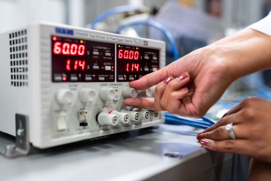
Controlling voltage output in a circuit means managing how much electrical pressure a source delivers to a load. The three most common methods are using a voltage regulator integrated circuit, building a voltage divider with resistors, or using a variable regulator like the LM317. The right choice depends on whether you need a fixed, adjustable, or high-current output.
What Is Voltage Output and Why Does It Matter?
Voltage is the electrical force that pushes current through a circuit. It is measured in volts. Most electronic components require a specific voltage range to operate correctly. Too much voltage can damage components. Too little voltage may prevent them from working at all.
Think of voltage like water pressure in a pipe. Components are designed for a certain pressure range. If the pressure is too high, the pipe bursts. If it is too low, the water barely trickles out. Controlling voltage output keeps your circuit within its designed operating range.
Power supplies often produce more voltage than a component needs. A wall adapter might output 12 volts, but your microcontroller only wants 5 volts. Without voltage control, you risk destroying the microcontroller the moment you connect it.
How Do Resistor Voltage Dividers Work?
A voltage divider is the simplest way to reduce voltage. It uses two resistors in series. The output voltage is taken from the connection point between them.
The formula for a voltage divider is Vout = Vin × (R2 / (R1 + R2)). R1 is the resistor closest to the input voltage. R2 is the resistor closest to ground. The output is measured across R2.
Voltage dividers work well for reference voltages and signal conditioning. They are cheap and easy to build. However, they have a serious limitation. The output voltage changes when you connect a load that draws current. The load acts like another resistor in parallel with R2, which shifts the divider ratio.
If your circuit draws only microamps, a voltage divider can work fine. If it draws milliamps or more, the voltage will sag. For powering components, voltage dividers are generally not a reliable solution. They are better suited for setting reference voltages or scaling sensor signals.
How Do Linear Voltage Regulators Control Voltage?
Linear voltage regulators are integrated circuits that maintain a constant output voltage. They take an unregulated input voltage and produce a steady, fixed output. Common examples include the 7805 for 5 volts and the 7812 for 12 volts.
These regulators work by using a transistor as a variable resistor. The regulator continuously adjusts the transistor to keep the output voltage stable. If the input voltage rises, the regulator drops more voltage across the transistor. If the input falls, it drops less.
Linear regulators are simple to use. You typically need only two small capacitors for stability. They provide clean, low-noise output. This makes them ideal for sensitive analog circuits and microcontrollers.
The main drawback is efficiency. The excess voltage is converted to heat. If you step down from 12 volts to 5 volts while drawing 1 amp, you waste 7 watts as heat. That requires a heatsink. For large voltage differences or high currents, linear regulators become impractical.





How Do You Use an Adjustable Voltage Regulator?
Adjustable regulators let you set the output voltage to any value within a specified range. The LM317 is the most common adjustable positive regulator. It accepts input from about 3 to 40 volts and can output between 1.25 and 37 volts.
The LM317 uses two external resistors to set the output voltage. The formula is Vout = 1.25 × (1 + R2/R1) + Iadj × R2. The adjustment pin current is small and often negligible in calculations.
To build an adjustable supply, you connect the input to your power source. The output goes to your load. The adjustment pin connects to the junction of two resistors between output and ground. Changing the resistor values changes the output voltage.
Using a potentiometer in place of the fixed resistor lets you adjust the output on the fly. This is useful for benchtop power supplies where you need different voltages for different projects.
Like fixed linear regulators, the LM317 dissipates excess voltage as heat. Higher input voltages and higher currents demand proper heatsinking. The maximum current is typically 1.5 amps, though some variants handle more.
What Are Switching Regulators and When Should You Use Them?
Switching regulators control voltage by rapidly turning a transistor on and off. They store energy in an inductor and capacitor during the on phase, then release it to the load during the off phase. By varying the duty cycle, they control the average output voltage.
Switching regulators come in three main types. Buck converters step voltage down. Boost converters step voltage up. Buck-boost converters can do either.
The key advantage of switching regulators is efficiency. High-quality designs achieve 85 to 95 percent efficiency. This means less heat and better battery life. A buck converter stepping 12 volts down to 5 volts at 2 amps wastes far less energy than a linear regulator doing the same job.
The tradeoff is complexity. Switching regulators require more external components, including an inductor, diodes, and specific capacitors. They also produce electrical noise that can interfere with sensitive circuits. Proper layout and filtering are essential.
For battery-powered devices, switching regulators are usually the right choice. For audio circuits or precision measurement equipment, the noise may be unacceptable. In those cases, a linear regulator or a switching regulator followed by a linear post-regulator works better.
How To Control Voltage Output In A Circuit With PWM
Pulse-width modulation, or PWM, is another method for controlling average voltage. Instead of producing a constant voltage, PWM rapidly switches the output between full on and full off. The ratio of on-time to off-time determines the average voltage.
The duty cycle is the percentage of time the signal is on. A 50 percent duty cycle produces an average voltage of half the supply. A 75 percent duty cycle produces three-quarters of the supply.
PWM is not true voltage control. If you measure with a multimeter, you see the average value. But the instantaneous voltage alternates between full supply and zero. Many loads respond to the average. LEDs dim smoothly with PWM. DC motors change speed. Heaters adjust temperature.
PWM does not work for loads that need steady voltage, like microcontrollers or sensors. Those require a regulator. But for power control, PWM is highly efficient because the switching transistor is either fully on or fully off, minimizing wasted energy.
Arduino boards and many microcontrollers have built-in PWM outputs. You can control the duty cycle in code. This makes PWM an easy software-based method for controlling power to motors, lights, and other loads.
What Factors Should You Consider When Choosing a Method?
The first consideration is current draw. Voltage dividers handle only tiny currents. Linear regulators handle up to about 1.5 amps with proper cooling. Switching regulators can handle much more, depending on the design.
The second consideration is efficiency. If your device runs on batteries, efficiency directly affects runtime. Linear regulators waste excess voltage as heat. Switching regulators conserve that energy.
The third consideration is noise. Linear regulators produce very clean output. Switching regulators produce ripple and high-frequency noise. Sensitive analog circuits may require additional filtering.
The fourth consideration is cost and complexity. A voltage divider costs pennies and uses two resistors. A switching regulator design requires a controller chip, inductor, diodes, capacitors, and careful PCB layout. Linear regulators fall in between.
Input voltage range matters too. Some regulators have maximum input limits. Exceeding them destroys the component. Always check the datasheet for your specific regulator.
No single method is best for every situation. Matching the method to your requirements is the core skill in circuit design.
Common Mistakes When Controlling Voltage Output
One common mistake is using a voltage divider to power a load. The output drops as soon as the load draws current. This leads to unexpected behavior and unreliable circuits.
Another mistake is forgetting about dropout voltage. Linear regulators require the input to be higher than the output by a minimum amount. The 7805, for example, typically needs at least 7 volts input to produce a stable 5 volts. If the input is too low, the output drops out of regulation.
Ignoring heat dissipation is another frequent error. Linear regulators convert excess voltage to heat. Without a heatsink, the regulator overheats and shuts down or fails. Calculate the power dissipation as (Vin – Vout) × Iload before building your circuit.
Bypass capacitors are also commonly omitted. Most regulators require small ceramic capacitors at the input and output for stability. Without them, the regulator may oscillate or produce noisy output.
Finally, many beginners exceed the maximum input voltage. Check the datasheet. A 7812 regulator rated for 35 volts maximum input will fail if you connect it to a 40-volt supply.
Frequently Asked Questions
What is the simplest way to reduce voltage in a circuit?
A resistor voltage divider is the simplest method, using just two resistors. However, it only works for very low-current applications like reference signals, not for powering loads.
Can I use a potentiometer to control voltage output?
Yes, a potentiometer can adjust voltage when used in a divider configuration or as the adjustment resistor on a regulator like the LM317. A bare potentiometer cannot handle significant current and will overheat if used to power a load directly.
What is the difference between linear and switching regulators?
Linear regulators provide clean, quiet output but waste excess voltage as heat. Switching regulators are more efficient and handle higher currents but produce electrical noise and require more external components.
How do I calculate the resistor values for the LM317?
Use the formula Vout = 1.25 × (1 + R2/R1). Pick a value for R1, typically around 240 ohms, then solve for R2 to get your desired output voltage.
